Vertical Divider
Musing on Competitive Technology
Samsung's QNED Displays
May 31, 2020
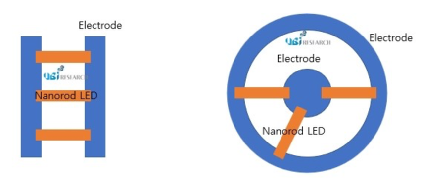
UBI having analyzed 41 patents reports that Samsung Display will use a circular electrode structure for the pixels of its QNED, or quantum dot nanorod LED displays also called QD 2.0. QNED will be comprised of thin-film transistor (TFT), pixel, quantum dot (QD) and color filter (CF). The TFT structure was described as 2Tr1C on the patents, vs. 3Tr1C structure for current driving. The pixel consists of a nanorod LED and electrode in an optical structure to efficiently used the light emitted from the LED and the electrode structure will be circular.
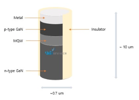
Figure 1: Nanorod LED Structure of Samsung's QNED Displays
Source: UBI Research
A reason for the circular circuitry could be the difficulty in accurately locating the nano rods, which will be IJP. Reports of alignment accuracy at 75% to 80%, would constrain the use of the technology. But a circular electrode structure could overcome the alignment limitation. Some of the patents showed applying an asymmetric wave on the circular electrode to improve the LEDs directional output UBI claimed. The nanorod LED will also be made using gallium nitride (GaN) and emit blue light. The size was estimated to be less than 1µm x 10µm. The surface of LED will include insulating film and device aligners. A Samsung Display spokesperson declined to comment on the matter.
Figure 2: Illustrations of Rectangular Electrode Structure and Circular Electrode Structure
(Left: Rectangular Electrode, Right: Circular Electrode)
Figure 2: Illustrations of Rectangular Electrode Structure and Circular Electrode Structure
(Left: Rectangular Electrode, Right: Circular Electrode)
Source: UBI Research
|
Contact Us
|
Barry Young
|


